Why impedance matching is critical in wireless communication

Maximum Power Transfer:

First of all we know that our goal for any design is to achieve optimum power efficiency. In other words we want to utilize most of our electrical power without wasting it in a form that is not beneficial.

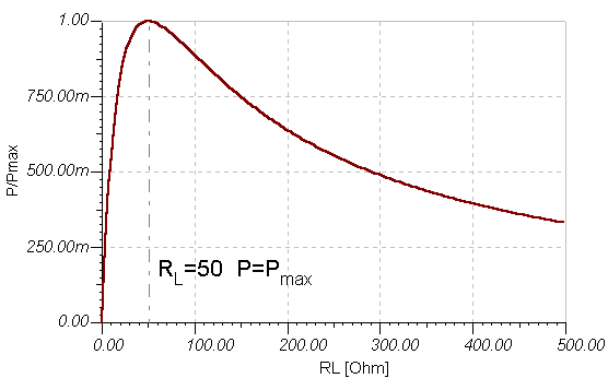
Maximum power transfer theorem states that power transfer will be maximum for a load if the resistance of that load will match the internal resistance of the source. Down below graph of Power vs RL shows maximum point when RL = Rs; where RL stands for load resistance and Rs stands for source resistance.Maximum power is dissipated across the load resistor when load resistance matches the internal resistance of the source which is 50 ohms in this case.

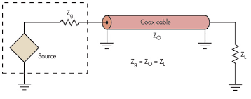
To get maximum power transmission we need impedance of source, coaxial cable and load to match i.e Zo,Zg,Zl.

Physical limitations of antenna designs:

First of all there are only few rated coaxial cables out there in the market. For some satellite communications we usually use 50 ohm coxial cable, for T.V we usually use 75 ohm coaxial cable. We do not have the ranges of coaxial cables with all the different impedance ranges.

Secondly our load has a certain impedance and so does our source, we to match all these impedances to get maximum power transfer.

Benefits of Impedance Matching

For sattlelite communication in particular, we have only so much power to deliver from the satellite partly because of sattlelite’s dependance on solar energy from the sum, we cannot afford to loose any power. We want to make sure that we set up conditions for maximum power transfer.

If we don’t match the impedance then the source will face reflected power that in turn can damage the source.

If line impedance and load impedance are matched then the line length does not matter, but if they don’t match then we will see a complex impedance as a function of line length.

In conclusion we will have maximum power transmission,high quality reception, less heat production, better standing wave ratio, more source safety, and more line length flexibility if we match the impedance.

If you have any questions please do not forget to ask

References

“MAXIMUM POWER TRANSFER THEOREM.” Maximum Power Transfer Theorem, http://www.tina.com/English/tina/course/11maxim/maxim.php.

Frenzel, Lou. “Back to Basics: Impedance Matching (Part 1).” Electronic Design, 4 May 2018, http://www.electronicdesign.com/communications/back-basics-impedance-matching-part-1.

How voltage supply ironically regulates the current in every circuit.

We all have worked with the power supplies, or else you are on the wrong website.

 The power supplies have a rating.

For this one one mode gives us a rating of 0-8V with 3 A of current.

This very statement seemed contradictory to me. We all were taught that we apply the voltage and the circuit decides with its Req values what current will flow through the circuit. How can a 8V supply decide how much current can my external circuit draw ? Isn’t ohms law V = IR, where current for a constant voltage is decided by the resistance of the circuit.

Turns out that the current that is supposed to be flown in our external circuit has to our voltage supply; when the current passes through the voltage supply, voltage supply checks and regulates the current.

For this power supply for example if the applied voltage at the external circuit is 8V and the external circuit want to draw current greater than 4A. The voltage source immediately will take a notice of it. This step is crucial. The voltage source will not allow more than 4A to flow through the external circuit.

As a result this voltage source will turn into a current source that is outputting a constant 4A. This makes a person understand why a voltage source has a current rating on it.

For questions and ambiguities please don’t hesitate to email me.

Multiplexing with Flying Capacitor

Introduction

Whether it be Digital or Analog, Multiplexing is basically switching to take in or throw out the desired input and output respectively. Of different techniques involved to switch between inputs or outputs, one such technique is called multiplexing with flying capacitor. It seems captivating when one imagines capacitors flying.

Circuit to be examined

Explanation

  1. First of all I will make a brief comment on the entire circuit. This circuit involves inclusion of two channels as inputs. We take one input at a time to our instrumentation amplifier which further takes the signal to sample hold circuit and analog to digital converter. Since we can only take one input at a time and we are playing with 2 channels as inputs, we need some sort of switching/multiplexing.
  2. Since Multiplexing is required to choose one input at a time from two inputs, we will use capacitors to perform this task. Hence analog multiplexing will be done with the capacitors.
  3. Now we will look at Channel B. Channel B with the difference from common mode voltage is charging the capacitor. Theoretically there is 0 resistance, and hence current is approaching infinity. But this information is not pertinent. The main point is that the capacitor is charging and charge is being stored inside the capacitor. So current flows into the capacitor until the capacitor charges up to ∆V.
  4. Now when capacitor is charged up to the desired ∆V value, we can make the capacitor go mobile. I will make a comparison with a real life example for a better understanding. Think of this capacitor like our power banks now a days; we charge them and when they are fully charged we can take them with us for giving our phones energy when required.
  5. Something very similar is happening here. The capacitor gets charged and now we can use it as our interim voltage source to our instrumentation amplifier.
  6. When this capacitor will get fully charged we will connect it to the input of the instrumentation amplifier(swapping the position of already placed channel A capacitor).
  7. This is how we firstly charge a capacitor, use its stored energy to act as an input source and swap it with the other capacitor when one gets discharged.
  8. This swapping of capacitor to change input sources at the instrumentation amplifier is a perfect example of low level analog multiplexing.

For questions and ambiguities regarding the concept please don’t hesitate to email.

References

Devices, A., Inc. (1986). Analog-digital conversion handbook. Englewood Cliffs (New Jersey): Prentice-Hall.