Introduction
Whether it be Digital or Analog, Multiplexing is basically switching to take in or throw out the desired input and output respectively. Of different techniques involved to switch between inputs or outputs, one such technique is called multiplexing with flying capacitor. It seems captivating when one imagines capacitors flying.
Circuit to be examined
Explanation
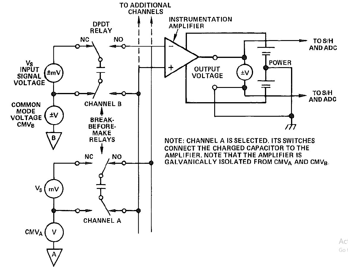
- First of all I will make a brief comment on the entire circuit. This circuit involves inclusion of two channels as inputs. We take one input at a time to our instrumentation amplifier which further takes the signal to sample hold circuit and analog to digital converter. Since we can only take one input at a time and we are playing with 2 channels as inputs, we need some sort of switching/multiplexing.
- Since Multiplexing is required to choose one input at a time from two inputs, we will use capacitors to perform this task. Hence analog multiplexing will be done with the capacitors.
- Now we will look at Channel B. Channel B with the difference from common mode voltage is charging the capacitor. Theoretically there is 0 resistance, and hence current is approaching infinity. But this information is not pertinent. The main point is that the capacitor is charging and charge is being stored inside the capacitor. So current flows into the capacitor until the capacitor charges up to ∆V.
- Now when capacitor is charged up to the desired ∆V value, we can make the capacitor go mobile. I will make a comparison with a real life example for a better understanding. Think of this capacitor like our power banks now a days; we charge them and when they are fully charged we can take them with us for giving our phones energy when required.
- Something very similar is happening here. The capacitor gets charged and now we can use it as our interim voltage source to our instrumentation amplifier.
- When this capacitor will get fully charged we will connect it to the input of the instrumentation amplifier(swapping the position of already placed channel A capacitor).
- This is how we firstly charge a capacitor, use its stored energy to act as an input source and swap it with the other capacitor when one gets discharged.
- This swapping of capacitor to change input sources at the instrumentation amplifier is a perfect example of low level analog multiplexing.
For questions and ambiguities regarding the concept please don’t hesitate to email.
References
Devices, A., Inc. (1986). Analog-digital conversion handbook. Englewood Cliffs (New Jersey): Prentice-Hall.
